
Knowledge Center
Design & DFM
Design for manufacturability, value engineering, geometry decisions that reduce cost, and how manufacturers can improve your drawings.
Design for Manufacturability — commonly abbreviated DFM — is the practice of designing parts and assemblies so they can be produced efficiently, consistently, and at the lowest reasonable cost without sacrificing function. It bridges the gap between engineering intent and shop-floor reality by considering manufacturing constraints early in the design process rather than after drawings are finalized.
DFM covers a wide range of decisions: choice of raw material, feature geometry, tolerances, surface finish requirements, and how a part will be fixtured and inspected. A design that looks clean on screen can carry hidden cost drivers — deep pockets with tight corner radii, unnecessarily tight tolerances, or exotic materials where a standard alloy would perform equally well.
For engineers, DFM is about closing the loop between what is designed and what is practical to build. Engaging your manufacturer early in the process is one of the most effective ways to apply DFM principles to your specific production environment.
DFM reduces manufacturing costs by eliminating unnecessary complexity before a part ever reaches the shop floor. Every tight tolerance requires an additional verification step; every deep, narrow pocket requires slower feeds, smaller tooling, and potentially multiple setups. By identifying and removing these cost drivers early, DFM compresses both cycle time and scrap rate.
Common cost-reduction levers include relaxing tolerances on non-critical features, standardizing hole sizes to common drill diameters, designing radii that match standard end mill sizes, and selecting materials that machine predictably without special tooling. These changes often have no effect on part performance but can reduce per-piece cost significantly.
The earlier DFM is applied, the greater the savings — changes at the design stage are inexpensive; the same changes after tooling or production has begun carry real cost. Buyers and engineers who involve their manufacturer at the prototype or pre-production stage consistently see better outcomes. Mikron works with customers during design reviews to surface these opportunities before they become production problems.
DFM review is most valuable as early as possible — ideally during the concept or detailed design phase, before drawings are released for production. At that stage, geometry, materials, and tolerances are still flexible, and changes carry little or no cost. A DFM conversation that happens at the prototype stage is useful; one that happens after production tooling is built is expensive.
That said, DFM is not a one-time event. It should be revisited when volumes increase, when a design migrates from prototype to production, when materials change, or when a cost-reduction initiative is underway. Parts that were acceptable at ten units per year may become costly to produce at a thousand units per year.
Practically speaking, the best time for a DFM review is when you send a drawing or model to your manufacturer for a quote. Any capable precision shop will flag features that add cost or risk. Mikron reviews incoming drawings with this lens and will raise potential design improvements as part of the quoting process, so customers have the information they need before committing to a design.
Yes — and a good manufacturer will. When a precision shop reviews an incoming drawing, experienced engineers and machinists often recognize features that add cost or machining risk without serving a functional purpose. Flagging those features and suggesting alternatives is a legitimate and valuable part of the manufacturing partnership.
Common recommendations include opening a tight tolerance on a non-mating surface, substituting a standard thread form for a custom one, increasing a corner radius to match a common end mill size, or redesigning a feature to eliminate a secondary setup. None of these changes typically affect how the part performs; they simply make it faster and more reliable to produce.
A buyer should feel comfortable asking their manufacturer for DFM feedback — it signals that you want a functional, cost-effective result rather than simply a drawing reproduced exactly. Mikron includes design feedback as part of its quoting process and welcomes early-stage conversations where design flexibility still exists. The goal is always a part that works as intended and is produced as efficiently as possible.
Tolerances drive cost in two distinct ways: they determine how the part must be machined, and they determine how the part must be inspected. A feature toleranced at ±0.001" requires slower cutting speeds, more careful setup, and higher-precision tooling than the same feature at ±0.010". Tight tolerances also force more rigorous inspection — coordinate measuring machines, air gauges, or custom fixtures rather than calipers — which adds time and cost per piece.
The problem is that tight tolerances often appear on drawings by default or habit rather than functional need. Engineers sometimes carry tolerances from a previous design without questioning whether they apply to the new context. Every tolerance on a drawing should be traceable to a functional requirement: a mating surface, a clearance fit, a sealing interface. If no such requirement exists, the tolerance is a cost driver without a corresponding benefit.
A useful discipline is to review each toleranced feature and ask: what happens if this is at the loose end of the tolerance band? If the answer is "nothing functionally important," the tolerance can likely be relaxed. Discussing this with your manufacturer before finalizing drawings is the most efficient way to catch unnecessary constraints.
Have a manufacturing question about your part?
Talk with the Mikron team or send us your drawings for review.
Material selection affects nearly every aspect of manufacturability: cutting speed, tool wear, surface finish achievability, fixturing, and post-processing requirements. Choosing a material primarily for its mechanical properties without considering machinability can significantly increase cycle time and per-piece cost.
Aluminum alloys are among the most machinable metals and are appropriate for a wide range of structural and enclosure applications. Free-machining brass and steel grades cut cleanly and quickly. Titanium, hardened steels, and exotic alloys like Inconel require slower feeds, specialized tooling, and more frequent tool changes — all of which increase cost. Engineering plastics vary widely: Delrin and nylon machine well; PEEK and filled composites are more demanding.
Material form matters too. Bar stock, plate, and extruded profiles each suit different part geometries. Choosing a near-net-shape starting material reduces the volume of material that must be removed, lowering cycle time and material waste. When a design is still flexible, it is worth discussing material options with your manufacturer — the performance requirements may be met by more than one alloy, and the cost difference can be meaningful at volume.

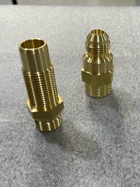
Part geometry directly controls how many setups a machinist needs, what tooling is required, and how long each operation takes. A part that can be fully machined in a single setup is inherently more efficient than one that requires three repositions and a secondary operation — each additional setup adds fixturing time, introduces potential for positional error, and increases total cycle time.
Specific geometry decisions with significant impact include: inside corner radii (smaller radii require smaller, slower tools), floor-to-wall transitions, depth-to-width ratios of pockets, draft angles on milled features, and whether critical features share a common datum. Parts designed with the machining process in mind — accessible features, consistent radii, logical datum references — simply take less time to produce and inspect.
Extruded profiles and standard structural shapes can often replace complex machined geometry when the function is structural rather than precision. Designing around standard stock shapes reduces material cost and machining time simultaneously. When you share a model or drawing early, a manufacturer can quickly identify geometry that will add time on the machine and suggest alternatives that preserve function.


Several recurring design features consistently add machining time and cost. Deep, narrow pockets require small-diameter tooling that must run at reduced feeds and speeds to avoid breakage — and often require multiple passes to reach full depth. Sharp internal corners cannot be produced with a rotating end mill; they require EDM or must be replaced with a radius, so unless a sharp corner is functionally necessary, it should always be radiused to match a standard tool size.
Long, thin features — thin walls, tall bosses, slender pins — are prone to deflection during cutting, requiring lighter passes and longer cycle times to maintain dimensional accuracy. Unbalanced parts that are difficult to fixture securely share the same problem. Threads in blind holes add tapping cycle time and increase the risk of tap breakage, especially in harder materials.
Surface finish requirements also drive time: an as-machined finish is fast, while a specified Ra roughness or decorative finish requires additional operations. Multiple datum references that are not mutually accessible force re-fixturing. By reviewing a drawing with these patterns in mind — ideally with your manufacturer — engineers can often eliminate the most time-consuming features without any functional trade-off.
Inspection is a cost that scales with complexity. Parts that are difficult to measure require longer inspection time, specialized gauging, and sometimes custom fixtures — all of which add to per-piece cost. Designing for inspectability means ensuring that every critical dimension can be measured efficiently with standard metrology equipment.
Practical guidance includes: establishing clear, accessible datum references so CMM probing is unambiguous; placing critical features so they are reachable without re-fixturing the part on the inspection table; avoiding toleranced features in recessed areas that require specialized probes; and consolidating related tolerances onto common datums to simplify the inspection plan.
Geometric dimensioning and tolerancing (GD&T) applied correctly can actually simplify inspection by making the functional requirement unambiguous — a true position callout tied to a defined datum scheme is faster to verify than a chain of linear dimensions requiring manual calculation. Engineers who think about how a part will be measured while they are still designing it tend to produce drawings that are both cheaper to inspect and more likely to yield parts that perform as intended. Discussing your inspection requirements with your manufacturer early helps align the drawing to the available metrology equipment.
Value engineering is a structured review process aimed at delivering the required function of a part or assembly at the lowest possible cost. Unlike simple cost-cutting, value engineering asks whether every design element, material choice, and process step is contributing to the part's function — and eliminates or simplifies those that are not.
In precision manufacturing, value engineering might identify that a multi-piece welded assembly can be replaced by a single machined part, that a tight tolerance exists on a non-critical surface and can be relaxed, that a specified material can be substituted with a less expensive alloy that meets the same performance requirements, or that a secondary finishing operation adds cost without meaningful benefit to the end application.
Value engineering is most productive when the manufacturer and customer collaborate openly. The customer understands the functional requirements; the manufacturer understands the cost structure. Together, they can identify trade-offs that neither would see independently. It is particularly valuable when a design is transitioning from prototype to production, where cost per unit becomes more sensitive. Mikron welcomes these conversations and can engage early in the design cycle or during a cost-reduction review on existing parts.
Ready to Discuss Your Project?
Mikron's team is available to review your drawings and answer questions specific to your part.