
Knowledge Center
Precision Sheet Metal
Laser cutting, punching, press-brake forming, bending allowances, and when to choose fabrication over machining.
Precision sheet metal fabrication is the process of cutting, forming, and finishing flat metal stock into structural and functional components with controlled dimensional accuracy. Unlike heavy structural fabrication, precision sheet metal work targets tight tolerances on formed features, hole patterns, and assembly interfaces — the kind of accuracy required for electronic enclosures, instrument panels, brackets, and equipment housings.
The process typically combines several operations: flat-pattern cutting (laser, punch, or shear), bending on a press brake, hardware insertion, and finishing such as powder coat, paint, or anodize. When a manufacturer performs all of these steps under one roof, the result is tighter control over accumulation of tolerances and faster turnaround than routing parts through multiple vendors.
For engineers and buyers, precision sheet metal is an efficient path to structural enclosures, panels, and brackets that need repeatable accuracy at both prototype and production volumes. Mikron performs precision sheet metal fabrication in Colorado Springs alongside CNC machining and welding.
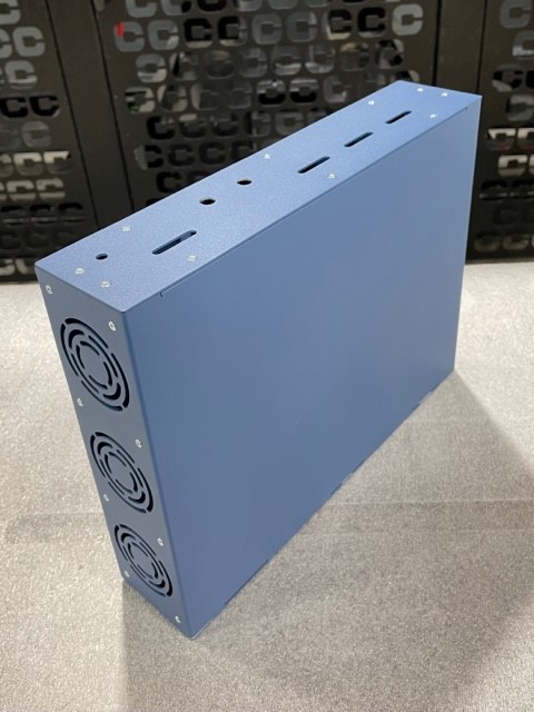
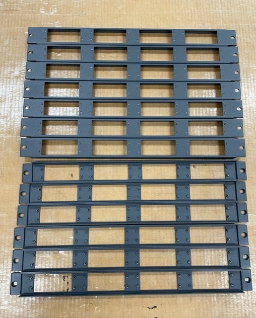
Sheet metal fabrication and CNC machining serve different geometry and volume profiles, and choosing the right process early saves significant cost. Sheet metal is the natural choice when a part is thin-walled, enclosure-like, or largely flat with formed features — enclosures, panels, brackets, chassis, and covers. These shapes would require removing enormous volumes of material from billet if machined, making sheet metal far more economical.
CNC machining is better suited to solid or complex three-dimensional geometry, tight bore tolerances, threaded features, and parts that require the structural integrity of solid stock. Many assemblies benefit from both: a machined chassis or mounting block combined with sheet metal enclosure panels, for example.
The decision also involves volume. Sheet metal tooling investment is relatively low, and laser cutting requires no hard tooling at all, making it accessible at prototype quantities. At higher volumes, the formed nature of sheet metal parts lends itself to consistent repeatability. When evaluating a new design, sharing the model or sketch with your manufacturer early allows them to recommend the most cost-effective process — or combination of processes — for the geometry and quantity involved.

Precision sheet metal fabrication draws on a sequence of complementary processes, each suited to a specific stage of part creation. Flat-pattern cutting — by laser, punch press, or shear — produces the blank from which the part is formed. Laser cutting dominates for complex profiles and prototype work because it requires no hard tooling and holds tight feature-to-feature accuracy. Punching is efficient for high-volume production of repetitive hole patterns. Shearing is used for simple straight-line cuts on rectangular blanks.
Press-brake bending forms the cut blank into three-dimensional geometry by clamping the material between a punch and die. Hardware insertion — PEM nuts, studs, standoffs — is typically performed after forming, pressing fasteners into pre-punched holes for flush, strong thread engagement without welding. Welding joins separate sheet metal components into assemblies, either by MIG, TIG, or resistance methods depending on material and joint requirements.
Finishing operations close out the process: deburring and edge-breaking for safety and aesthetics, powder coat or liquid paint for corrosion protection and appearance, silk-screening or laser engraving for labeling. A shop that performs all of these steps in-house offers better schedule control and tighter tolerance management across the full process chain.
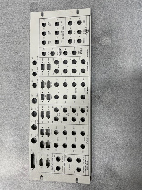
Laser cutting, punching, and shearing are all methods for producing flat sheet metal blanks and cut features, but they differ in capability, speed, and tooling requirements. Laser cutting uses a focused high-energy beam to cut profiles with high accuracy and virtually no tooling cost — the cutting path is entirely software-driven. It handles complex contours, close-tolerance hole patterns, and fine features well, making it the preferred method for prototypes and low-to-mid volume production across a wide range of shapes.
Punch pressing uses hardened steel punches and dies to stamp holes, slots, and forms into sheet metal at high speed. It is highly efficient for repetitive hole patterns at volume, but each feature shape requires a dedicated punch-and-die set. Per-hit cycle time is very fast once tooling exists, but tooling cost makes it less economical for one-off or highly varied work.
Shearing is the simplest operation: a straight guillotine-type blade makes a single linear cut across the sheet. It is used to produce rectangular blanks from larger stock quickly and economically. Shearing cannot produce curves, interior cutouts, or complex profiles — it is a preparation step, not a finishing operation. Most precision sheet metal fabricators use all three methods, selecting the appropriate process for each feature type and production volume.
Press-brake forming bends sheet metal by clamping a flat blank between a top punch and a bottom die, then driving the punch downward to force the material past its yield point into a permanent angular bend. The angle of the bend is controlled by how far the punch travels into the die — a process called air bending — or by fully seating the material against the die geometry in coining or bottom-bending modes. Modern CNC press brakes program each bend sequence, back-gauge position, and tonnage, producing highly repeatable results across a production run.
The key variables in press-brake work are material type, thickness, bend radius, and bend sequence. Each material has a characteristic springback — the tendency to partially unbend after the punch is withdrawn — which the operator compensates for by overbending slightly. Bend radius affects both appearance and structural integrity; too tight a radius can crack harder alloys. Bend sequence matters because later bends can collide with the press-brake tooling if not planned in the correct order.
For designers, understanding press-brake mechanics helps produce drawings that are straightforward to bend. Consistent bend radii, adequate flange lengths, and thoughtful feature placement relative to bend lines all reduce setup time and scrap. Consulting your fabricator's standard bend radius chart for each material thickness is a simple way to avoid costly design revisions.
Have a manufacturing question about your part?
Talk with the Mikron team or send us your drawings for review.
Bend design decisions made early in the drawing process have a direct impact on fabrication cost, accuracy, and yield. The most important consideration is bend radius: each material and thickness combination has a minimum bend radius below which cracking becomes likely. Using your fabricator's standard tooling radii — rather than arbitrary values — avoids the need for special dies and simplifies the bending sequence.
Flange length is equally important. If a flange is too short, the press brake cannot grip it securely, which produces inconsistent bend angles and potential part damage. A general rule is that minimum flange length should be at least twice the material thickness plus the bend radius, though specific minimums depend on the tooling set in use.
Feature proximity to bend lines deserves careful attention. Holes, slots, and cutouts placed too close to a bend line will distort during forming. Keeping features a minimum distance — typically at least twice the material thickness — from any bend line preserves their geometry. Finally, consider the bend sequence: complex parts with multiple bends in different planes must be designed so each bend can be reached by the press-brake tooling without interference from previously formed flanges. Sharing a 3D model with your fabricator before finalizing the drawing is the most reliable way to validate the bend sequence and catch these issues early.
Material thickness influences nearly every aspect of the sheet metal fabrication process: cutting method, bend radius, press-brake tonnage, hardware selection, weld parameters, and the structural performance of the finished part. Thicker material generally requires more cutting power, tighter bend radii become less achievable without cracking, and heavier-gauge parts demand more press-brake force — meaning not every shop's equipment can handle the full thickness range a design might require.
For laser cutting, thicker material reduces cutting speed and can affect edge quality and kerf width, which in turn affects hole-to-edge accuracy. For bending, each additional thickness increment increases springback variability and requires recalibration of the bending sequence. Hardware — PEM fasteners, for example — is sized by material thickness, so changing gauge late in the design process can invalidate the fastener selection.
Structural considerations run in the opposite direction: thicker material increases stiffness and load capacity but also weight. For enclosures and panels, engineers often balance structural requirements against weight targets and fabrication cost. Standard sheet gauges vary by material — steel, aluminum, and stainless each have their own gauge conventions — so specifying by decimal thickness rather than gauge number reduces ambiguity. Discussing your thickness requirements with your fabricator early ensures their equipment and standard tooling set are matched to your design.


Yes — sourcing fabrication and welding from a single manufacturer can reduce lead time, cost, and quality risk on sheet metal weldments. When both operations occur under one roof, there is no inter-vendor shipping, no re-inspection on receipt, and less ambiguity about which supplier is responsible when a fit issue arises.
The practical benefit is most visible on enclosures and multi-piece weldments where weld distortion, formed dimensions, and hardware placement must all align. A fabricator who also does the welding can adjust fixturing and weld sequence to control distortion from the start, rather than discovering an interface problem after parts have shipped across the country.
For purchasing professionals, single-source sheet metal fabrication and welding also simplifies program management: one purchase order, one schedule, and one point of contact. Mikron performs precision sheet metal fabrication and welding in Colorado Springs for customers who need those processes managed by one team.
Ready to Discuss Your Project?
Mikron's team is available to review your drawings and answer questions specific to your part.