
Knowledge Center
Tolerances & Precision
What machining tolerances mean, how GD&T works, why tighter isn't always better, and how to specify critical dimensions.
A machining tolerance defines the permissible variation from a nominal dimension — it is the acceptable range within which a feature must fall for the part to function as intended. Every physical manufacturing process introduces some variation, so tolerances communicate how much variation is acceptable rather than demanding a theoretically perfect dimension. A tolerance is expressed as a bilateral range (±0.005″), a unilateral allowance (+0.000/−0.010″), or through a geometric control in a GD&T framework. Understanding tolerance is fundamental to bridging design intent and production reality: a dimension without a tolerance is incomplete, because the manufacturer has no objective acceptance criterion. For engineers, specifying tolerances is one of the most consequential decisions made during drawing creation — it directly governs fit, function, interchangeability, inspection cost, and ultimately price. Reviewing tolerances carefully before releasing a drawing to production is a straightforward step that prevents costly surprises downstream.
Achievable tolerance is governed by a combination of machine capability, tooling, workholding, material behavior, and part geometry working together — no single factor dominates in isolation. A high-rigidity machining center with tight spindle bearings and thermal compensation can hold closer tolerances than an older general-purpose mill, but only if the fixturing keeps the part stable and the material doesn't flex or deflect under cutting forces. Tooling condition matters enormously: worn cutters introduce runout and chatter that erodes dimensional consistency. Material plays a role too — harder, more homogeneous metals like steel and titanium often machine more predictably than soft alloys prone to smearing, or composites with abrasive fibers. Part geometry is a practical limit as well; thin walls, deep bores, and long slender features all introduce compliance that works against tight tolerances. When specifying tight dimensions, engineers should confirm with their manufacturer that the combination of machine, process, and material can realistically achieve the requirement — and request process capability data when it matters most.
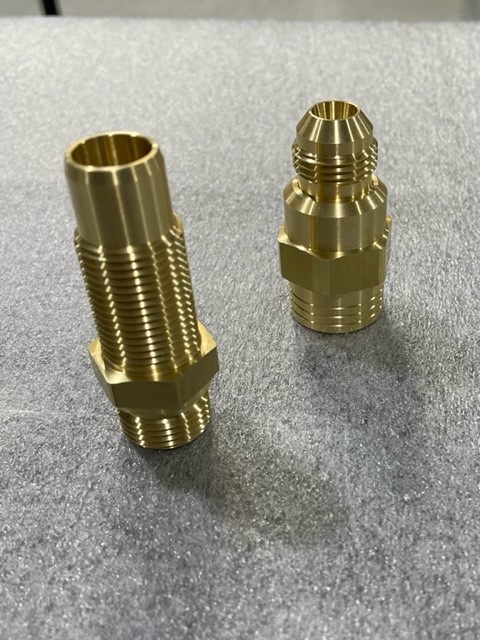
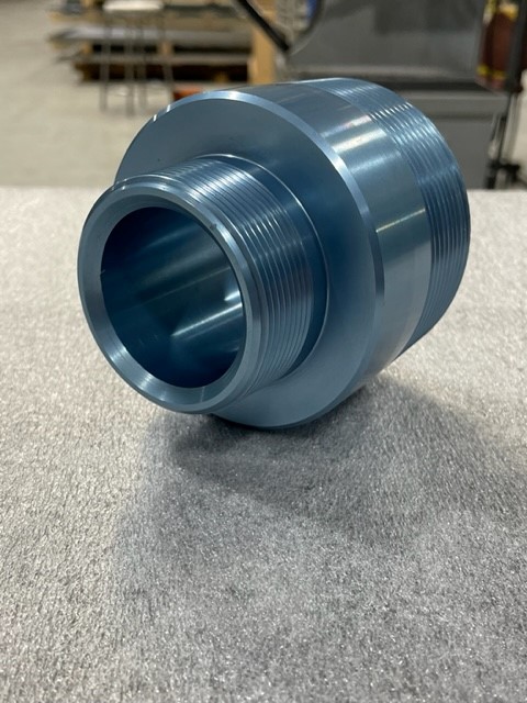
Applying tight tolerances universally to a part is one of the most common — and expensive — mistakes in manufacturing drawings. Only a small subset of dimensions on any given part are truly critical to fit, function, or assembly. When every dimension carries a tight callout, the manufacturer must slow down cycle times, use more precise setups, perform more intensive inspection, and accept higher scrap rates — costs that are passed directly to the buyer. Beyond cost, over-tolerancing can actually create quality problems: very tight tolerances on non-critical features can cause a conforming part to be rejected even though it would function perfectly well. The discipline of tolerance analysis — identifying which dimensions are functionally critical and loosening everything else to the widest acceptable range — reduces unit cost, shortens lead time, and simplifies inspection without compromising performance. A good rule of thumb is to start with your manufacturing partner's standard tolerances as the default and tighten only those dimensions where function genuinely demands it.
Tighter tolerances increase cost through several compounding mechanisms. First, they typically require slower feed rates, lighter cuts, and more setups — all of which increase machine time. Second, tighter tolerances demand more sophisticated workholding and sometimes dedicated fixtures to eliminate part movement between operations. Third, inspection burden rises: a dimension held to ±0.001″ may require CMM measurement rather than a simple go/no-go gauge, adding time and equipment cost per piece. Fourth, scrap and rework rates climb because the acceptance window is narrower — statistical variation that would be benign on a loose tolerance becomes a nonconformance on a tight one. These costs scale nonlinearly: moving from ±0.005″ to ±0.001″ can multiply the cost of a single feature several times over. Practically speaking, engineers should perform a tolerance stack-up analysis to determine the minimum tightness that ensures assembly function, and then add only a modest safety margin. Communicating openly with your manufacturer about which tolerances are driven by hard functional requirements — versus conservative habit — often reveals opportunities to reduce cost without any sacrifice in part performance.

Critical-to-quality (CTQ) dimensions are the specific features on a part whose variation directly impacts function, safety, fit, or regulatory compliance. The concept comes from Six Sigma methodology but applies broadly to any precision manufacturing context. On a hydraulic fitting, the sealing bore diameter and thread form are CTQ features; the overall body length might carry a much looser tolerance because it doesn't affect sealing performance. Identifying CTQ dimensions early — ideally during design review — allows engineers to focus tolerance tightening where it matters, align inspection resources to those features, and communicate clearly to the manufacturer which dimensions require heightened process control. CTQ callouts are often flagged on drawings with a specific symbol or noted in a revision block, and they form the basis of first-article inspection and ongoing statistical process control sampling. Buyers working with a new supplier should confirm that the manufacturer's quality plan explicitly addresses every CTQ dimension identified on the drawing before production begins.
Have a manufacturing question about your part?
Talk with the Mikron team or send us your drawings for review.
Geometric Dimensioning and Tolerancing (GD&T) is a symbolic language standardized under ASME Y14.5 that communicates not just the size of a feature but its allowable variation in form, orientation, location, and runout relative to a datum reference frame. Traditional plus/minus tolerancing is simple but limited — it treats each dimension independently and can inadvertently over-constrain or under-constrain a design. GD&T is more expressive: a true position callout, for example, defines a cylindrical tolerance zone around the theoretically exact location of a hole, which gives more usable tolerance than a square ±X/±Y zone of the same specification. This matters practically because a part that passes GD&T inspection will genuinely assemble correctly, while a part toleranced only with coordinate dimensions might pass inspection yet still fail in assembly due to combined geometric errors. GD&T is particularly valuable for parts with close-fitting mating features, datum-sensitive assemblies, and any component subject to regulatory inspection. Engineers who invest in GD&T training produce drawings that are clearer, less ambiguous, and ultimately cheaper to manufacture and inspect correctly.
The clearest approach is to use a combination of explicit notation and drawing organization to distinguish critical dimensions from general ones. Many engineers use a "CRIT" flag, a boxed dimension, or a separate critical characteristics table that lists each controlled feature by zone or label. ASME Y14.5 GD&T feature control frames inherently communicate criticality through their callout precision, but a supplementary note or title block entry that defines default tolerances helps the manufacturer immediately understand the baseline. Revision blocks should document when a critical dimension changes and why, providing traceability for quality records. It is also good practice to include a notes section that identifies any regulatory, safety, or interface requirements driving specific callouts — this context helps manufacturers make intelligent decisions during setup and inspection planning rather than treating all features identically. When releasing drawings to a new supplier, a brief design review meeting to walk through critical dimensions is time well spent; it prevents misinterpretation and builds shared understanding of what the part must do.
Geometry is one of the most underappreciated constraints on tolerance achievement. Thin-walled features deflect under cutting forces, making it difficult to hold diameter or flatness consistently. Deep internal bores require long boring bars that have more runout and flex than short, rigid tooling. Parts with significant internal cavities can relax after machining as residual stresses redistribute, shifting dimensions that were correct at the time of cutting. Re-entrant features, undercuts, and compound angles may require multiple setups or specialized tooling that introduces cumulative positioning error with each refixturing. Asymmetric parts clamp unevenly, introducing distortion that shows up as flatness or parallelism deviation. Understanding these geometry-driven limitations early in design allows engineers to make targeted adjustments — adding material where rigidity is needed during machining, designing features to be accessible in fewer setups, or tolerancing flexible features appropriately. Sharing 3D models with your manufacturer during the design phase invites this kind of manufacturability feedback before the drawing is finalized, saving time and cost later. Mikron's team is available to review part geometry and flag potential challenges early in your project.
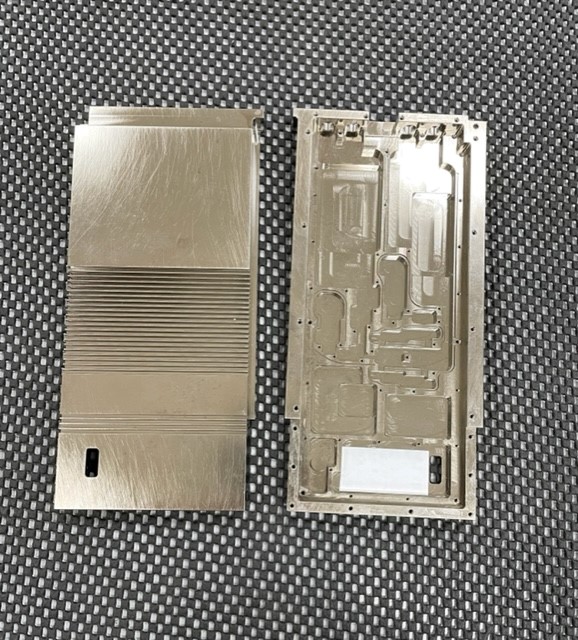

Material choice has a direct and sometimes dramatic effect on whether a machined part holds its dimensions through the manufacturing process and in service. Coefficient of thermal expansion (CTE) is a key variable: aluminum expands and contracts roughly twice as much as steel per degree of temperature change, which matters both during machining — where cutting heat is generated — and in service environments with thermal cycling. Some aluminum alloys retain residual stress from the rolling or extrusion process that releases during machining, causing the part to warp or shift after material is removed. Free-machining alloys often include lead or sulfur additions that improve chip breakage but can reduce corrosion resistance or mechanical strength. Plastics and composites present their own challenges: many absorb moisture and change dimensions measurably with humidity, and they have much lower stiffness than metals, making them prone to deflection during cutting. Material certification and lot consistency matter too — property variations between heats or batches can shift machinability and dimensional predictability. Selecting material in close consultation with your manufacturer, especially for tight-tolerance applications, ensures the final choice supports both the functional requirements and the production process.


Inspection of precision machined parts spans a range of methods matched to the type of feature, tolerance requirement, and production volume. Hand tools — micrometers, calipers, height gauges, and bore gauges — remain workhorses for straightforward dimensional checks and are fast and cost-effective for features where their measurement uncertainty is adequate relative to the tolerance. Go/no-go gauges provide efficient pass/fail verification for threaded features, pin holes, and other features of size that must accept a mating component. Coordinate Measuring Machines (CMMs) are the standard for complex geometric verification: a CMM probes the part surface at programmed points and computes actual feature locations, orientations, and form errors against the drawing's nominal values and tolerances, including GD&T callouts. Optical comparators and vision systems are well suited to flat profiles, small features, and thread forms. Surface roughness profilometers measure finish to verify Ra or Rz callouts. For tight-tolerance or high-stakes parts, first-article inspection combines all relevant methods into a comprehensive dimensional report before production quantities are approved. The appropriate inspection method is always a function of what the tolerance is, what the risk of nonconformance is, and what the drawing explicitly requires.
Ready to Discuss Your Project?
Mikron's team is available to review your drawings and answer questions specific to your part.