
Knowledge Center
CNC Machining
How CNC machining works, when to use it, what affects cost, and how to choose the right machine shop for your project.
CNC machining — Computer Numerical Control machining — is a subtractive manufacturing process in which pre-programmed software directs cutting tools to remove material from a solid workpiece and produce a finished part. The "subtractive" distinction matters: unlike casting or additive processes, CNC starts with more material than the final part contains and precisely carves away the excess.
The process is valued for its repeatability, dimensional accuracy, and compatibility with a wide range of engineering materials — metals, plastics, and composites alike. Once a program is validated, every subsequent part follows the same toolpaths, which makes CNC machining equally well-suited to one-off prototypes and high-volume production runs. For buyers, understanding this foundation helps set realistic expectations around lead time, cost drivers, and design requirements before a project reaches the shop floor.

The process begins with a CAD model of the finished part. A CAM (Computer-Aided Manufacturing) programmer uses that geometry to generate toolpaths — the precise sequences of moves a cutting tool follows to remove material. Those toolpaths are translated into G-code, the instruction language CNC controllers read. The machine then executes those instructions, moving the spindle and workpiece in coordinated axes while coolant and chip management systems protect the cutting edge and surface finish.
Setup is where much of the skilled labor lives: selecting cutting tools, fixturing the part securely, and proving out the program before cutting production stock. Multi-axis machines can reposition the part automatically between operations, reducing the number of manual setups required for complex geometry. For engineers, the practical takeaway is that design features directly influence the number of setups and tools needed — both of which affect cost and lead time. Mikron's team at its Colorado Springs facility works with customers during the quoting stage to identify opportunities to simplify setups without compromising function.
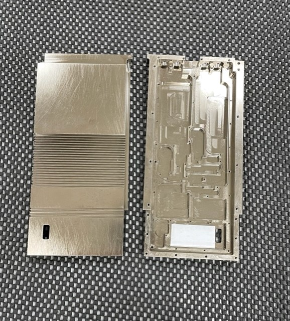
CNC milling and CNC turning are the two foundational machining processes, and the right choice depends primarily on part geometry. In milling, the cutting tool rotates while the workpiece remains fixed (or moves linearly). This makes milling the natural choice for prismatic shapes — blocks, brackets, housings, and plates — where flat surfaces, pockets, slots, bores, and contoured profiles need to be created on multiple faces.
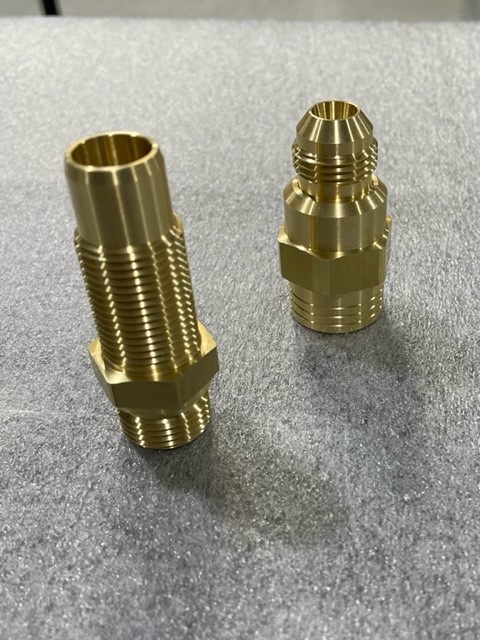
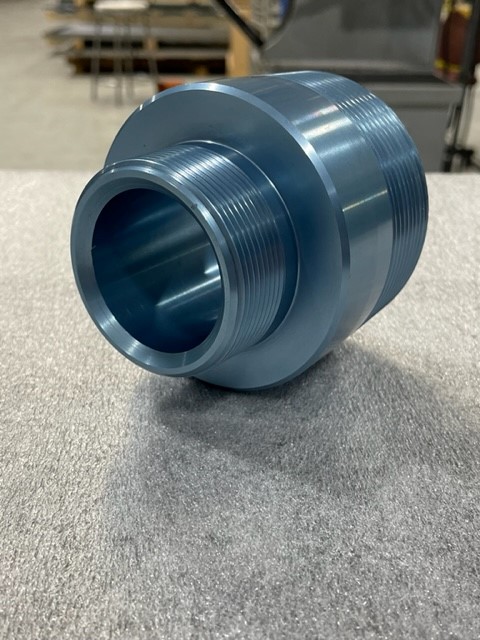
In turning, the workpiece rotates against a stationary cutting tool on a lathe. Turning excels at cylindrical and symmetric geometries: shafts, bushings, fittings, threaded fasteners, and similar round components. Many parts benefit from both processes; a turned shaft might need a milled flat or cross-hole, which can be achieved on a turn-mill center in a single setup. When specifying a new part, sharing the full CAD model and function with your machine shop early allows their engineers to recommend the most efficient process — or combination of processes — before programming begins.
Milling is the better choice whenever a part's primary geometry is non-cylindrical. Housings, enclosures, plates, brackets, and structural components that require machined features on flat or contoured faces are natural candidates. If a part has multiple intersecting features — pockets, through-holes at varied angles, bosses, or complex external profiles — milling can address them in a single setup on a multi-axis machine.
That said, the distinction blurs on modern equipment. Turn-mill centers allow cylindrical parts to receive milled features (flats, cross-holes, keyways) without being re-fixtured, reducing setup time and improving positional accuracy between features. A practical rule of thumb: if a part's primary axis of symmetry is rotational, start with turning and add milling as needed. If the part is predominantly prismatic or features are distributed across multiple non-parallel faces, milling is likely the primary process. When geometry is ambiguous, a DFM (design for manufacturability) conversation with your machine shop early in the design cycle can identify the most cost-effective routing before the program is written.

CNC machining is one of the most versatile manufacturing processes available, spanning industries from aerospace and defense to medical devices, electronics, and industrial automation. Common component categories include structural housings and enclosures, fluid-system fittings and manifolds, precision shafts and spindles, brackets and mounting hardware, heat sinks, jigs and fixtures, and prototype parts across virtually any discipline.
What unites these applications is a need for dimensional accuracy, material integrity, and repeatability that casting, injection molding, or fabrication alone cannot deliver. The process also handles tight-tolerance features — precision bores, threaded inserts, mating surfaces — that are difficult or impossible to achieve by other means at low-to-mid volumes. For purchasing professionals evaluating suppliers, it's worth confirming that a candidate shop has experience with your specific component type and material, since tooling strategies, fixturing approaches, and inspection methods vary significantly between, say, a thin-walled aluminum housing and a stainless-steel hydraulic fitting.
Have a manufacturing question about your part?
Talk with the Mikron team or send us your drawings for review.
A complete print package is the foundation of an accurate quote and a successful first article. At minimum, a machine shop needs a dimensioned 2D drawing (with tolerances, surface finish callouts, and any GD&T) paired with a 3D CAD model in a neutral format such as STEP or IGES. The drawing governs; the model aids programming and inspection planning.
Beyond geometry, shops need to know the material and any required material certifications (mill certs, for example), applicable finish or coating specifications, quantity and delivery expectations, and any regulatory or quality requirements — ITAR, AS9100, customer-specific inspection plans, and so on. Functional context also helps: knowing that a bore is a bearing seat or that a surface is a sealing face allows the machinist and programmer to prioritize those features appropriately. Incomplete information at the quoting stage usually results in assumptions that add cost or cause rework. The more complete the package you provide upfront, the faster and more accurately a shop can respond — and the fewer surprises appear at first article inspection.
Yes — and this scalability is one of CNC machining's most commercially important attributes. A single validated program produces the first prototype and, later, the thousandth production unit with the same geometry and tolerances. There is no tooling investment analogous to injection mold or casting die, which makes CNC cost-competitive at low-to-mid volumes and eliminates the risk of locking into tooling before the design is finalized.
Prototype runs also serve as de-facto process qualifications: any manufacturability issues surface on a small batch before volume commitments are made. For programs that will eventually scale, working with a single source from prototype through production reduces transition risk — the shop already understands the part, has proven fixtures, and has identified any recurring challenges. This continuity matters particularly for programs under ITAR or with customer-specific quality plans, where re-qualifying a new supplier carries real cost and schedule implications. Mikron has supported customers at every phase from initial concept through sustained production runs, and that continuity is a deliberate part of its service model.
Several geometric and material factors compound machining difficulty. Thin walls and floor sections deflect under cutting forces, making it hard to hold tolerance without specialized fixturing and reduced chip loads. Deep, narrow pockets limit tool reach and restrict coolant delivery, which accelerates tool wear and increases the risk of chatter. Features that require the tool to approach from multiple angles may demand additional setups or five-axis capability. Very tight tolerances — particularly on features that interact — require careful thermal management and in-process gauging.
On the material side, hard alloys, work-hardening stainless steels, and high-temperature alloys like titanium or Inconel wear tooling quickly and generate significant heat, both of which affect surface integrity and dimensional stability. Long, stringy chips (common in some aluminum alloys and plastics) can re-cut the surface if chip evacuation is inadequate. Identifying these challenges at the design stage — rather than after the program is written — is where a DFM-focused machine shop adds real value. Many difficult features can be redesigned slightly without any functional compromise, reducing cost and improving first-article yield.
Machining cost is primarily driven by time: the total minutes the machine and operator are occupied producing your part. Setup time — loading material, fixturing, proving the program — is largely fixed per batch regardless of quantity, which is why unit cost drops as volumes increase. Cycle time, the minutes actually cutting material, is driven by part complexity, number of features, required surface finish, and material machinability.
Beyond machine time, cost drivers include tooling consumption (hard materials wear tools faster), the number of setups required (each repositioning adds time and skilled labor), inspection requirements (tight tolerances need more measurement steps), and material cost itself — which can range from a few dollars per pound for commodity aluminum to hundreds for aerospace-grade titanium. Finish operations like anodizing, plating, or painting add further cost and lead time. For purchasing professionals building a business case, the most effective levers are simplifying geometry to reduce setups, relaxing tolerances on non-critical features, and consolidating parts where possible. A quick DFM conversation with your shop before finalizing the design often returns more savings than any negotiation afterward.
The highest-impact cost reductions come from design decisions made before the part ever reaches a machine. Tolerancing only the features that genuinely require precision — mating surfaces, bearing bores, sealing faces — allows the shop to run tighter processes where they matter and faster where they don't. Applying unnecessarily tight tolerances across the entire drawing forces slow feeds, frequent in-process measurement, and higher scrap rates.
Standardizing feature sizes to common tool diameters (rather than specifying a 0.377" slot that requires a custom tool) avoids special tooling charges and long lead times. Designing internal corners with generous radii, avoiding deep narrow pockets, and minimizing the number of part orientations needed to machine all features each reduce setup count and machine time. Consolidating what might have been two or three separate parts into a single machined component can eliminate assembly labor and tolerance stack-up simultaneously. Material selection also matters: easier-to-machine alloys cut faster and wear tools less, meaningfully reducing cycle time. Sharing functional intent with your machine shop and asking for DFM feedback is one of the most cost-effective steps an engineer can take early in a program.
Have a manufacturing question about your part?
Talk with the Mikron team or send us your drawings for review.
Machining time is essentially the sum of all the tool movements required to produce every feature on a part — and geometry determines how many movements are needed and how quickly they can safely execute. A simple prismatic block with a few through-holes machines in a fraction of the time required for a complex housing with multiple deep pockets, contoured surfaces, and intersecting bores, even if the two parts are similar in overall size.
Complex external profiles and 3D contoured surfaces require many closely spaced toolpath passes to achieve the required form and finish, which compounds quickly. Every additional setup — repositioning the part to access a new face — adds fixturing time, potential datum shift, and skilled verification steps. Feature count matters too: twenty tapped holes take longer to drill and tap than two, even on a machine that changes tools automatically. For engineers, the practical implication is that geometry review during design — asking "does this feature need to be here, and does it need to be this complex?" — directly translates to cycle time and cost. Features that add manufacturing complexity without adding function are worth eliminating or simplifying before the program goes to the shop.
Tool length-to-diameter (L/D) ratio is the core constraint. A cutting tool is cantilevered from the spindle; as the ratio of tool length to tool diameter increases, deflection under cutting forces grows, chatter becomes more likely, and the achievable tolerance on walls and floors degrades. Reaching the bottom of a deep, narrow pocket may require a long, slender end mill that can only take light cuts — dramatically increasing cycle time compared to a shallow pocket machined with a short, rigid tool.
Chip evacuation compounds the problem. In a deep pocket, chips have a long path to travel before clearing the work zone. If they pack in around the cutting edge, they re-cut the surface, generate heat, and accelerate tool wear. Coolant delivery — critical for surface finish and tool life — is also restricted by the geometry. From a design standpoint, pockets shallower than 3:1 depth-to-width are generally easy to machine; beyond that, cost and risk rise progressively. Where deep pockets are functionally required, designing in a larger floor radius, increasing wall draft slightly, or stepping the pocket geometry can each help. Sharing this kind of functional context with your machine shop opens a productive conversation about what can be modified without affecting performance.
Every internal corner in a milled pocket is produced by a rotating end mill, which means it will always have a radius equal to at least half the tool diameter — a perfectly sharp internal corner is geometrically impossible with a rotary cutter. If a drawing specifies a sharp internal corner without acknowledging this constraint, the shop must either use an extremely small tool (fragile, slow, expensive) or note it as a deviation.
The practical guidance: design internal corner radii to match standard tool sizes where possible, and specify the largest radius the mating component will accommodate. A 0.125" radius requires a smaller, more fragile tool than a 0.250" radius; the larger the radius, the more robust the tool and the faster the operation. Where a sharp internal corner is genuinely required for a mating part, consider designing in an undercut or a relief groove rather than asking for a zero-radius corner. This is a common DFM conversation — communicating functional intent (why the corner needs to clear a mating feature, for instance) helps the shop propose a solution that satisfies the assembly requirement without forcing an impractical tooling choice.
Every operation — a tool change, a setup reorientation, a secondary process, an additional inspection step — consumes machine time, labor, and sometimes external processing lead time. When those operations exist to produce features that serve no functional purpose, the cost they add is pure waste with no performance return. Common examples include cosmetic chamfers or radii on hidden surfaces, surface finishes finer than the application requires, tolerances tighter than mating part clearances demand, and features that were carried over from a previous design without revisiting their necessity.
Operations that require the part to leave the shop and return — anodizing, plating, heat treating — add not just cost but scheduling risk and lead time variability. Where finish operations are genuinely required, batching them with other parts going to the same vendor can reduce per-part cost. The broader discipline is treating the drawing as an engineering document rather than a wish list: every note, tolerance, and feature specification should exist because a functional requirement demands it. Periodic design reviews — especially as a product matures from prototype to production — often surface operations that made sense at the prototype stage but can be relaxed or eliminated in volume. Your machine shop should be a willing participant in that conversation.
Start with quality system credentials. ISO 9001:2015 certification establishes that a shop has documented processes, change control, and internal audit discipline — not just good intentions. For defense or government-adjacent work, ITAR registration is non-negotiable. Ask whether certifications are current and which registrar issued them; a certificate number you can verify independently is worth more than a logo on a website.
Beyond credentials, evaluate equipment breadth relative to your part mix. A shop with both milling and turning capability — ideally with multi-axis machines — can handle complex geometry and minimize outside processing. Ask about their inspection infrastructure: CMMs, surface finish measurement, and first-article reporting capability signal a shop that can demonstrate conformance rather than simply asserting it. Responsiveness and communication quality during the quoting process are often predictive of how the shop behaves when a problem arises mid-program. Finally, consider continuity: a shop experienced in taking parts from prototype through production gives your program a single institutional knowledge base rather than forcing a re-qualification when volumes scale. Mikron has operated in Colorado Springs since 1985, offering CNC milling and turning, sheet metal fabrication, and welding under one roof — a useful starting point for programs that benefit from single-source continuity.
Ready to Discuss Your Project?
Mikron's team is available to review your drawings and answer questions specific to your part.